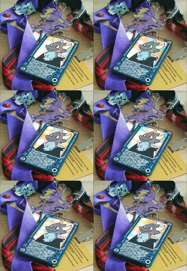
"I should make something for the con."
The idea had been rattling around in my head a while to make something for my first con. I wanted something small but unique to hand out to my friends and people I met, and above all else it had to be cheap, because I wanted to hand them out for free. The criteria were fairly simple - it had to be something cool, but I wanted it to be at least somewhat useful, not just a blinking light. And I definitely didn't want it to be a throwaway thing that ends up in the bin after the con.
Lots of ideas came to mind - flashlights, calculators, the kind of pocket trinkets you'll get at any tradeshow. Which was part of the problem - so boring! Time wore on and I found myself with about two weeks to go before the con. I had to pick an idea and run with it or I'd miss the chance altogether.
Luckily, like most tech-oriented people, furries suffer from the biological imperative to accumulate lanyard swag. Pins, badges, anything that you can hang on a lanyard is a popular commodity. So, who wouldn't love an RGB backlit lanyard tag? It's a highly visible conversation starter, it turns out. More importantly, I'd dealt with LED matrixes before, and with so little time I wanted a project that wasn't going to have unexpected hurdles with new technology. So off I went to design an RGB backlit nametag.
General Design
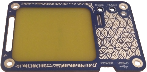
The design was simple: two credit-card sized PCBs, one which held all the electronics, and one that served as a faceplate and light diffuser. A slot in one end would allow running it through a lanyard or putting it on a ring, and a mounting point in each corner is used to fasten together the sandwich. I used inexpensive M3 4mm tall brass inserts meant for inserting into 3D prints, and a pair of very stubby M3 philips-drive screws, one in each side, to provide a nice flat fastening between boards. The electronics board was done in 1.0mm FR4 PCB thickness to reduce weight and thickness of the final badge, while the faceplate was done in standard 1.6mm FR4 as that's JLCPCB's shortest turnaround and lowest cost option.
FR4 PCB is usually a translucent yellowish colour, but you can't tell because it's covered by a layer of copper on each side, and a coloured solder mask on top of that. By removing an area of solder mask and the copper underneath on both sides of the faceplate, it leaves a translucent window that the RGB array can shine through. Unbeknownst to me, the FR4 from this manufacturer has a manufacturer mark inside the laminate. So if you see a little red "K" in the translucent window, now you know why :) This isn't a new idea by any means either - here's a word clock using the same shine-through PCB trick, from back in 2019.
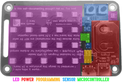
The internal electronics board is a green PCB with an entirely surface-mount design. JLCPCB charges extra for double-sided assembly, and since the back of the PCB was facing out I wanted to keep the assembly to only one side. I used a microcontroller I was familiar with, the ATtiny1616datasheet. This is Microchip/Atmel's latest iteration of the AVR core. It's very familiar if you've ever worked with an Arduino or it's derivatives, and Spence Konde has done a very nice job making them Arduino-compatible with megaTinyCore. The Tiny0/1 family uses a one-wire UPDI programming interface - I got a nice programmer for it from Tindie for less than $30. There's a tiny SMD header on the electronics board that exposes it, if you wish to program it yourself.
The following sections will go over what the major functional "blocks" of circuitry are doing, along with some of the decisions and mistakes made along the way. If you'd like to skip over the hardware side and jump straight to software, click here.
Power Supply
Powering the project was the first concern. Obviously, it needed to be portable. I quickly discarded the idea of AAA batteries - too bulky and heavy to comfortably fit on a lanyard. The obvious choice was some form of lithium battery. I would have loved to use one of the many, many, many different six-pin all-in-one protection and charge control chips that are dirt cheap and common. Unfortunately, getting lithium rechargeables in Canada kind of sucks - shipping is a nightmare, and they're expensive as a result. Plus, I had to take these through the TSA - I flew to Edmonton, and I have a feeling security might take a dim view to thirty individual lipo cells in my carry-on.
The unfortunate solution, in terms of small size, power density, and airline security friendliness was primary (non-rechargeable) coin cells, size CR2032 - these are frequently used in airtags and garage door openers, so they are common and inexpensive. The battery provides ~3V and a capacity of 235mAh @ 2V, although this capacity rapidly decreases if you're sourcing currents greater than a couple tens of milliamps. It's held in an SMD cradle, with a PCB contact point for the battery ground. It can be replaced, with some disassembly of the name tag to facilitate poking it out.

I was quite concerned that, once the battery was dead, someone might not see an obvious way to replace it and throw it out. I wanted users to see there was a way to power it beyond just it's battery lifespan. The awkward compromise was including a USB-C header for 5V input. This does not charge the non-rechargeable coin cell, thanks to a couple diodes that isolate the two different power inputs from each other. The USB-C also has 5.1K resistors on each of the CC1 and CC2 pins pulling them to ground to comply with USB-C power delivery for sink devices. This is kind of counterintuitive, since most people would see it and think, huh, guess this charges it? My thinking was that it could be used as an ambient light, or a night light, while plugged into a USB-C charger.
This left the awkward situation of having two working voltages - 5V, and 3V. But isn't there someone you forgot to ask? The green and blue LEDs in RGB will probably have a forward voltage greater than 3V. This is where the TX4310Bdatasheet comes into play. It's a charge pump that provides 3.3V output from a wide 1.8V-5V input range. It's inexpensive, available in a very small SOT-23-6 package, and only requires three small capacitors to function: two decoupling capacitors on the input and output, and a 2.2uF switch capacitor between the C+ and C- pins of the IC.
There wasn't a ton of space to work with, so the lack of inductor was appreciated. The current this pump can put out is quite limited (especially at 5V input), but using PWM it shouldn't be sourcing too much current at once. A single-pole, double throw (SPDT) switch is used to break the power input connection (USB or battery) to the TX4310B. I wanted to absolutely minimize any residual current drain on the already meagre battery.
The LEDs
While the power section is tidy, it's pretty boring - the main attraction is of course the RGB matrix. And this was probably my first huge fucking mistake. See, I had previously worked with multiplexed and charlieplexed LED matrices. So I thought, "to hell with those digitally addressable LEDs", and opted to design my own matrix using RGB packages with independent Red, Green, and Blue channels. Quick math: 5 * 4 matrix = 20 LEDs * 3 channels = 60 LEDs total to multiplex. Sad kobold noises.

There are 60 LEDs, and the MCU only has 20 pins, so multiplexing is a necessity. There's some minor considerations since this is an RGB matrix, where the LEDs are not all equivalent. Namely the forward voltage of the individual red, green, and blue diodes are different. In order to drive them at their recommended current and get equal brightness from each colour, we'll need to different levels of current for each channel.
The LEDs I used were available at an astounding price of $0.04 each in 100+ quantities. They have a a fairly reasonable datasheet. The blue and green channels are specified at the same min/max forward voltages, so they can use the same drive levels. The red diodes are specified at a minimum 2V, maximum 2.4V forward voltage. Digikey has a nice simple calculator to give you a series resistor value based on forward voltage and input voltage here. Using the minimum forward voltages as a worst-case, I came up with a value of 47 ohms for the blue and green channels, which works out to about 10.5mA of current at VF = 2.8V. To save on the bill of materials, I used two 47 ohm resistors in series (~94 ohms) for the red channel. This works out to around 13.5mA current at VF = 2.0V.
These resistor values (47 ohm each for blue/green, 94 ohm for red) keep the maximum current going through the LEDs to well within the maximum current on the datasheet. It also keeps us well within the 40mA source-sink limits of the ATtiny1616's IO pins (found on page 505 of the datasheet). It might not be as bright as it could be, but better to leave some breathing room.
In order to keep the multiplexing addressing simple, the badge uses an 11 pin drive setup: each row of 4 RGB LEDs uses a common channel, numbered from 1 through 5. Two of the four LEDs in each channel are set up in a common anode configuration, with all anodes connected in common to the channel, while the other two are set up in a common cathode configuration, with all cathodes linked in common to the channel. Two sets of RGB channels are used, allowing the two LEDs configured the same way (common anode or cathode) to be independently controlled. These are numbered R1/R2, G1/G2, and B1/B2.
To light an individual LED, we first set all 11 pins (the six RGB channels + 5 row channels) to input, or the high-impedance (hi-Z) state. This prevents current from being source/sunk by the IO pins, turning off all the LEDs. We then pull the row channel pin either HIGH (3.3V) or LOW (0V), depending on which LED we want to light. This allows each RGB channel (e.g. G1 or B2) to control two LEDs, by flipping the row channel state and the RGB channel state. We pull the matching RGB channel pin we want to light (R1/2, G1/2, B1/2) the opposite to what the channel is - if the channel is HIGH, we pull the RGB channel LOW, and vice-versa.

For those not familiar with it, charlieplexing is a way of multiplexing that takes advantage of the diode part of Light Emitting Diode. By flipping the polarity of the power applied, two LEDs in opposite polarities can be individually lit. The GIF here represents one row channel (CH1) and one RGB channel. Adding a second RGB channel takes the pin use count from 4 (CH1, R, G, B) to 7 (CH1, R1, R2, G1, G2, B1, B2), allowing control of four RGB diodes per row channel (or 4 * 3 = 12 diodes total). Doubling those four LEDs (by adding another row) then only costs 1 pin, needing only 8 pins to in turn drive 8 * 3 = 24 diodes total. It becomes very "cheap" in IO terms to expand the matrix further.
Each of the row channel and RGB channel pins was hooked up to a digital IO pin on the MCU. The software will handle pulling them up, down, or floating at Hi-Z. This is not the most efficient multiplexing that could have been done - this was a naive attempt, and it should be possible to multiplex these with fewer pins (although perhaps not with separate drive currents). However, this system made the addressing scheme pretty easy to handle, and avoided any weirdness with tri-state using diodes with mixed forward voltages.
A total of 8 current-limiting resistors are used. A 47 ohm resistor is put on each of the G1, G2, B1, and B2 lines. Two resistors in series are used for the red channels R1 and R2, for a total of 94 ohms each. Don't forget these, or you'll quickly burn out either the LEDs themselves, or the ATtiny IO pins.

An alternative I'd look at in the future is using addressable RGB LEDs. These have a controller integrated inside and can communicate via one or two wire interfaces to handle all the colour mixing and PWM themselves. It'd be a heck of a lot easier (albeit probably marginally more expensive), and saves a lot of time and effort offloading the LED control. But hey, 60 individual diodes matrixed with one MCU, never done that before. And somehow, it works ^-^
One final note on the manufacturing aspect. Matrices like these (oh jeez) are one of those rare opportunities to copy-paste traces and layout elements. It's very satisfying to see the next set of traces snap perfectly into alignment after a quick CTRL-C, CTRL-V, even after mirroring. If you ever design something similar, I definitely recommend a smiliar "modular" approach to layout, as it'll make keeping everything aligned and routable that much easier.
The Sensors

I didn't want the project to be just "fancy blinking lights" - I wanted to include some greater form of interactivity. With only 11 pins used for the matrix, there were still plenty of pins left for other goodies. I settled on three different measurements - temperature, ambient light level, and sound level. These should have been easy integrations, but my own overthinking and poor design left much to be desired. Chiefly, I chose to use an IO pin to power the sensors, thinking it would let me save power by powering the sensors down. This caused some problems.
The easiest of the three sensors to deal with was the temperature sensor. This was the Microchip MCP9700Adatasheet sensor, which takes 2.3V-5.5V input and provides a linear voltage level out of the VOUT pin. The 9700A has a 500mV (0.5V) offset at 0 degrees Celsius. It has a linear response of 10mV per degree Celsius and an accuracy of +/- 2 degrees. This is easily measurable with the 10-bit ADC on the ATtiny1616, which has approximately a 3mV step (based on 1024 steps @ 3.3V).

The ambient light sensor is an Everlight ALS-PT19datasheet. This is a phototransistor with sensitivity that approximates human eye response. Adafruit offers this part on a small breakout in series with a 10K resistor. I used a 5.1K resistor, which should have been larger to provide a better response range, and a 100nF loading capacitor. The loading capacitor is on the datasheet, but Adafruit leaves it off the breakout. Like the thermal sensor, it uses the 10-bit ADC to convert an analog voltage level ALS to a value in range 0 ... 1023.
The sensor would have done better with a higher resistance >10K, particulary since it's being driven at 3.3V. The curves in Fig 2 on page 5 of the datasheet showing the voltage versus loading resistance are really all you need to look at. It also introduced some noise into the SPOW line driving all three of the sensors, resulting in some light sensitivity appearing in all three, whoops.
The microphone was where the majority of problems occurred. My first interest in electronics was in the audio side, and it has given me lifelong anxiety when dealing with high-impedance signals. I used an inexpensive Zilltek ZTS6117datasheet MEMS microphone with an integrated pre-amplifier, according to the datasheet. I was wary of the output level, and rather than do what the datasheet suggested, I tried to add an op amp. This turned out to be a big mistake - first, I used a poor choice of biasing resistors - 5.1K was probably far too low, leading to impedance issues. Furthermore, I biased at 1/2 voltage, then fed it into an op amp set up with a gain of two. This meant the output was sitting at the +V rail most of the time, only dipping slightly on the negative peaks. To make matters worse, a couple 100nF decoupling capacitors were not enough to keep noise out of the SPOW line, resulting in noise on the op amp power and input signal biasing to be amplified. The "sound" sensor was now a "sound and light" sensor. I ought to have left well enough alone, and just used the 2.2uF decoupling capacitor directly into an ADC pin, with maybe a high-value (~33K) pull-down resistor to ground.
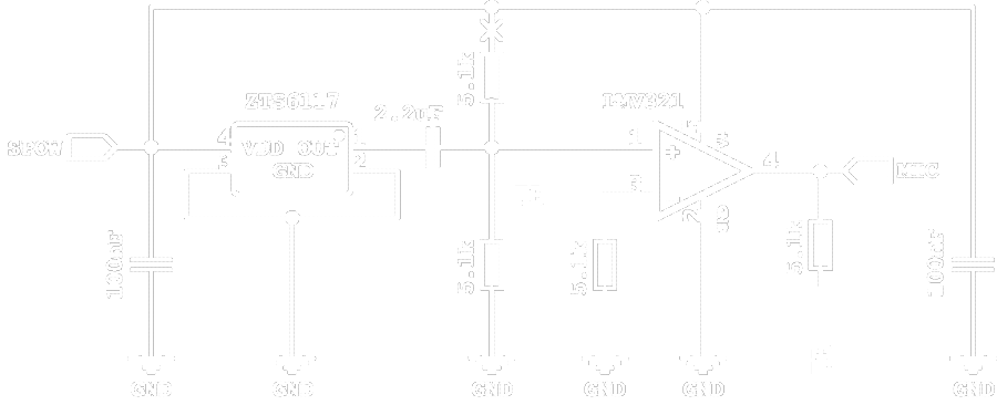
This section was saved, somewhat, by cutting the trace connecting SPOW to the input divider. This just left a 5.1K pull-down on the AC-coupled pull down. After doing this, I finally started getting some ADC readings that weren't 1023. The 5.1K resistor pulled the level down substantially, to the point that snapping my fingers generated at most a couple of steps (3-12mV swing), even after the 2x gain amplification. Even with the bias cut, the LMV321 op amp I was using definitely picked up the SPOW noise on the power input, and it displayed noticeable sensitivity to sudden changes in light level.
I had for the most part written off the sound portion of the board. It had very low sensitivity and would not pick up shouting, or even tapping on the board. Directly blowing into the sensor area would produce ~100mV of swing, but I considered this a failure. I cut the traces on all the boards and did what I could to make it functional, but my hopes were not high. It turns out I underestimated the power of a couple hundred watts of amplification playing EDM, which drove it quite effectively in that 100mV range. A learning experience for sure, but an unexpected victory too.
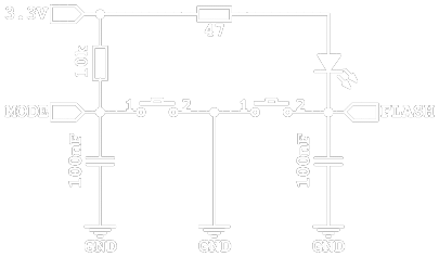
For user interfacing, two tactile switches were included. These are simple single-pole, single throw (SPST) switches in a normally-open configuration. Since 100nF SMD capacitors are fractions of a penny and take up a tiny amount of space, I included a couple to help with debouncing the switch inputs. The MODE button pulls the MODE pin to GND, which otherwise is pulled up by a 10K resistor. It is digitally read as a HIGH/LOW value.
The FLASH button is actually doing multiple duties. First, it allows current to flow through the white flashlight LED and the 47 ohm current limiting resistor. It also pulls the FLASH pin of the MCU low; it normally slowly floats up to ~2V through leakage in the LED. This tells the MCU when the flashlight is enabled, or when the user tries to enable the strobe. Because of the debounce capacitor, the flashlight LED does flash dimly on first power up due to the charge current. It's barely noticeable unless you look directly at the LED phosphor while flipping the switch.
The tactile switches electrically worked nearly perfectly; but the physical implementation had a couple problems. First of all, the buttons I got had a shaft length of 5.2mm. This turned out to be an absolute dream fit, in that fully assembled the buttons sat very nearly flush with the faceplace. This kept them from being pressed while the badge was bouncing around which was a plus. However, the button material itself was not the hard ABS-style plastic I expected. It was more like a soft, compressable TPU rubber. This meant that they needed more (and more equally spread) force to press, making it very difficult to use without an allen key, pen, or other small pointy object handy.
Lesson learnt - those buttons that look hard and plastic-y in the catalogue might actually be soft and rubbery. The datasheet doesn't mention material(s) anywhere, but I'm guessing the force levels (160gf, 250gf, 300gf, etc) correlate to different shore hardnesses of the rubber buttons. In the future I'd probably look at 6-7mm length buttons to make them easier to use, or preferably capacitive touch buttons directly on the PCB itself.
The MCU
Having talked about the power, LEDs, and sensors, there's not much to say about the MCU hardware-wise. It has a 10uF and 100nF decoupling capacitor on the input VDD line, which is more than the datasheet recommendation. It also has an extra 100nF decoupling capacitor on the SPOW line, for all the good it did.>_>; The ATtiny1616 uses a one-wire programming interface called UPDI. A 470 ohm resistor is placed on the PROG UPDI pin. This resistor isn't mentioned in the datasheet, and doesn't appear on the ATtiny evaluation boards, or even some of the third party boards. However, it is recommended by Spence Konde here.
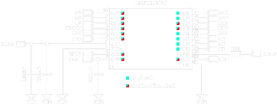
The most important thing to note here is the analog/digital multiplexing of the 1616 itself. All of the sensors, like MIC, ALS, and TEMP are attached to pins with analog (i.e. ADC) input. The pins that are digital only are relegated to driving the LED matrix - PB2/3, and the port C (PC) pins. They only need three states there - HIGH, LOW, and High-Z (input, floating). Pin numbering on the ATtinyX16 series is kind of wonky due to the port A pins wrapping around (i.e. PA3 on pin 19 and PA4 on pin 2), and the pin numbering used in Arduino is different again.
The MCU comes in a small 20-pin VQFN package, and includes a lot of the bells and whistles you'd expect: 10 bit ADC, 8 bit DAC, 256B EEPROM, 2KB RAM, 16KB of program storage, on-board oscillator (woo, no crystal!), and a lot of multiplexing to give flexibility of pin choice. It's a powerful little thing, and more than enough for most 8-bit MCU needs. In quantities of 100, you can find it for about $0.65 per piece, which is expensive but within the budget I set - I don't mind paying for the convenience of having flexible hardware and third-party software libraries.
The Software
With the hardware out of the way, let's talk about the software. What you'll find here is somewhat cleaned up, abbreviated version of the code on the board. There wasn't a lot of time for cleanup so the code on the boards is as rough as it gets while being functional. They aren't locked, you're free to dump out the original code if you have one of the boards and a UPDI programmer.
The display draws a single pulsed pixel at a time, using one of the four available colours: Green, Red, Blue, or None (not lit). An integer x value can be converted into a row pin (CH1 ... CH5) with subtraction. The magnitude of the y value is used to determine whether the channel pin will be HIGH or LOW. This gives the correct x and a ballpark y figure; the exact pin required for the y is based partially off the colour value. Using the modulo of y, we can determine whether to use the R1/G1/B1 channel or the R2/G2/B2 channel. The colour channel pin is pulled to the opposite potential of what the row channel pin is pulled. If the colour is none, a small delay for "dark" time is run instead.
// Draw one pixel of one colour at X/Y. Colours: 0 = G, 1 = R, 2 = B, 3 = None
void draw(int x, int y, int colour) {
	wipe();
	if (colour < 3){
		int row = 10 - x;
		int colour_channel = colour + 3;
		if (y % 2) {
			colour_channel = 16 - colour_channel;
		}
		pinMode(row, OUTPUT);
		pinMode(colour_channel, OUTPUT);
		if (y > 1) {
			digitalWrite(row, LOW);
			digitalWrite(colour_channel, HIGH);
		} else {
			digitalWrite(row, HIGH);
			digitalWrite(colour_channel, LOW);
		}
	} else {
		// Adjust for appropriate darkness
		delayMicroseconds(50);
	}
}
The wipe() function here wipes the display by setting all pins to their input, or high-impedance mode. This ensures that only one pixel is drawn to the screen at any given time, limiting the absolute amount of current being sunk at once.
While I'm using digitalWrite() and pinMode() here, you really shouldn't. It's very slow compared to manipulating ports directly (i.e. PORTA |= b00000010). Speed here is important - we're using persistence of vision to trick our eyes into seeing colours, and that only works if it's changing too fast for our mushy brains to discriminate. The darkness delay will depend on the speed that the matrix is cycling at. Too short and the dimming won't be noticeable, too long and it'll produce noticeable flashing as it slows down the entire drawing routine for every pixel.
In order to draw shades of different colours, four cycles are used, with each cycle representing one of the four basic colours. For example, the colour cyan is made by combining green and blue: a bright cyan might be pulsed as GBGB, while a dark cyan might be GNBN (N being None). Using four pulses is a compromise between the amount of time it takes to render (which must be fast) and the variety of colours available. With four pulses, all primary and secondary shades are possible, plus many tertiary shades. It also allows darker tones of primary and secondary shades, and light primary tones (i.e. pink, light blue, light green) since it can use R+G+B as white.
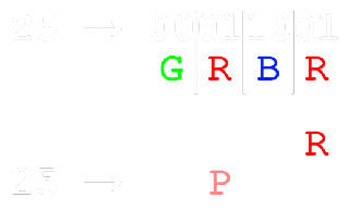
A handy side effect of using four cycles of four possible colours is that we can represent it easily using an 8-bit integer. A single pulse can be described using two bits: 00 = G, 01 = R, 10 = B, 11 = N. A single four-pulse shade then is 2 * 4 = 8 bits wide. This doesn't necessarily mean it has 256 colours of course - different pulse orderings should produce the same colour regardless of order. An abbreviated palette is available here in a TXT note, which I used for most of the project. The cycles are done in-sync for all pixels of the array. This means that it draws the first pulse of all twenty pixels, before then drawing the second pulse over all twenty pixels, then the third, and finally the fourth.
// Return an int 0 - 4 representing a single discrete pulse
int shade(int colour, int cycle){
  int rgbn = colour >> (cycle * 2);
  return (rgbn & 3);
}

// Draw all pixels a solid colour, drawing all four cycles for a shade
void solid(int colour){
	for(int cycle = 0; cycle < 4; cycle++){
		for(int x = 0; x < 5; x++){
			for(int y = 0; y < 4; y++){
				draw(x, y, shade(colour, cycle));
			}
		}
	}
}
So, you're actually seeing discrete separate pulses of red, green, and blue light, but your eyes can't process them fast enough. They blur together, and form a shade through the additive colour model. A simple function, shade(int colour, int cycle) returns the correct base colour for a given cycle. It simply returns the two-bit RGBN colour by shifting and masking the input colour for the correct cycle. Then, a loop can be used from [0 ... 3] to run over each "step" of the cycle and display the correct colour.
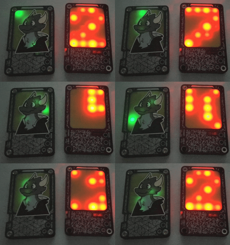
The first ten modes of the badge are just solid colours. These are pulled from an global array of length 10, using the mode number [0 ... 9] as an index. The next four modes are pride flags of various sorts. These are static - they each have a method that simply sets the colour of each pixel as needed for the given flag. The first dynamic mode is random pixels, which is a good demonstration of how I handled buffers and timing for the other dynamic modes.
// Slowly randomize the display state and display it
// STATE[][] is a global 2D integer array (5x4), initialized to 0
// COLOURS[] is a global 1D integer array that serves as a palette
// DELAY is a global integer initialized to 0
void random_pixels(){
	if(DELAY == 0){
		STATE[random(0,5)][random(0,4)] = COLOURS[random(0,31)];
		DELAY = 30;
	} else {
		DELAY--;
	}
	for(int cycle = 0; cycle < 4; cycle++){
		for(int x = 0; x < 5; x++){
			for(int y = 0; y < 4; y++){
				draw(x, y, shade(STATE[x][y], cycle));
			}
		}
	}
}
A global 2D integer array STATE is used as a "buffer" to hold the colours that should be displayed on the matrix. The buffer is drawn every time random_pixels() is called. Due to the DELAY variable, the buffer is only changed every 30 calls, providing a brief time displaying a static matrix before the next change. When DELAY is equal to zero, a random X and Y index in the STATE buffer are changed to a random colour from the COLOURS array. DELAY is then reset to 30. The random generator is seeded using the temperature, light, and sound sensors at initial startup, so they should generate consistently different patterns in the output.
The "green rain" mode (aka matrix rain) is very similar, but uses two delays. One longer delay has a chance to create a new green pixel (a "raindrop") in the STATE at X = 0 and a random Y value. A second shorter delay is used to shift the entire STATE down one X value. This shorter delay itself has a bit of randomization, allowing the rain to fall faster or slower. This is pretty effective for making a non-repeating pattern with variable sparseness depending on the randomization bounds and delays. With a swapped colour palette and reversed X-shift direction, it'd probably also work well for flames.
As a final example, the temperature sensor mode uses a larger STATE buffer, but only displays part of it. A 3D array called DIGITS is used to store the digits, with the first index being the number [0 ... 9], and the next two representing a 5x4 binary character of the digit. The temperature sensor value is read and converted to degrees Celsius, and split into two digits. These are used to look up the correct character map for the digit, which is copied into the STATE_XL variable, with a one-pixel gap between the characters.
// Display the current temperature as a two-digit number of degrees C
void temperature(int colour){
	if(SENSOR_DELAY == 0){
		float temp = ((analogRead(16) * (3.3 / 1023.0)) - 0.5) * 100.0;
		int degrees = round(temp);
		int digit1 = (degrees / 10) % 10;
		int digit2 = (degrees % 10);
		for(int x = 0; x < 5; x++){
			for(int y = 0; y < 4; y++){
				STATE_XL[x][y] = DIGITS[digit1][x][y];
			}
		}
		for (int space = 0; space < 5; space++){
			STATE_XL[space][4] = 0;
		}
		for(int x = 0; x < 5; x++){
			for(int y = 0; y < 4; y++){
				STATE_XL[x][y + 5] = DIGITS[digit2][x][y];
			}
		}
		SENSOR_DELAY = 8000;
	} else {
		SENSOR_DELAY--;
	}
	int scroll_position = round((SENSOR_DELAY / 1000) * 9) % 9;
	for(int cycle = 0; cycle < 4; cycle++){
		for(int x = 0; x < 5; x++){
			for(int y = 0; y < 4; y++){
				if(STATE_XL[x][y + scroll_position]){
					draw(x, y, shade(colour, cycle));
				}
			}
		}
	}
}
The sensor reading is taken on a long interval, and during that interval the display will slowly scroll through all available Y values. I haven't included the degree symbol and "C" in the example code here, the actual code uses a 20 pixel wide buffer (4 * 4 = 16 + 4 spaces). This code also allows text of any colour, passed along as an input to the method temperature(int colour). This mode was definitely the most attention-getting; something about scrolling text makes me people stop and look. It works fairly well, with some caveats: it isn't the most accurate (+/- 2 degrees), and it isn't programmed to handle negative temperatures, or temperatures >99 degrees. But given this was Edmonton in July, I think it was probably okay :)
The rest of the sensors were handled similarly. The next mode is an amplitude visualizer - it draws a bar (from red to green in four steps) equal to the sound volume over 100 samples, then performs an X-shift similar to the matrix rain. This forms an amplitude waveform on the badge that will match up with very loud music. The mode after that is a solid-colour backlight that randomly changes colour when sound amplitude breaks a certain pre-specified threshold. The last mode is a dimming mode driven by the ambient light sensor. It always displays the colour white (integer 27), but adds in additional delay between every four cycles depending on the ambient light level. It will decrease the delay (getting brighter) in dark environments, get dimmer as light level increases, and cut off completely once a threshold is passed.
Some final errata: the state of the MODE and FLASH buttons is checked at the beginning of each loop. These have some software debounce to detect double-taps and long-holds. Long-holding the MODE button returns you to MODE 0 - solid red backlight. Double tapping the FLASH button quickly will enable a strobe effect by pulling the FLASH pin LOW. This strobe is timed based on how quickly you press the button. When the MODE changes, it's written to the first byte of the EEPROM. This saves it, even when powered down. When the device is powered on, the first byte the EEPROM is read to recover the current mode. The badge will also power-down the SPOW sensor power line if in a mode that doesn't require the sensors (i.e. all except the last four).
Conclusions
Despite some hiccups, I'm still very happy with how this project turned out. It was a ton of fun to be able to hand out some hardware I designed myself. And the positive reactions I got from friends and people I met made it absolutely worth the time and effort. Of the thirty that were ordered: One was claimed by me; one was a testing dummy; and four of them suffered manufacturing faults. I think this was down to a clogged paste dispenser at the factory or a bad time during reflow, as all four failures have multiple dry MCU pins. This means 24 of them got handed out at the convention. If you're one of those lucky 24, it was nice to meet you! If not, I'll be back next year, and I have a lot more time to plan now ^^
Thanks for reading,
~Akaath